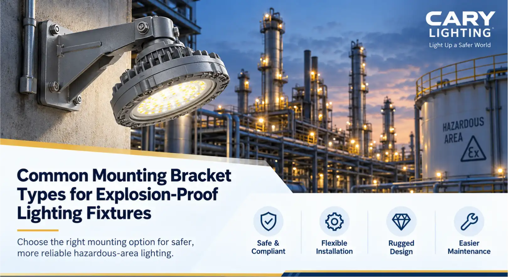
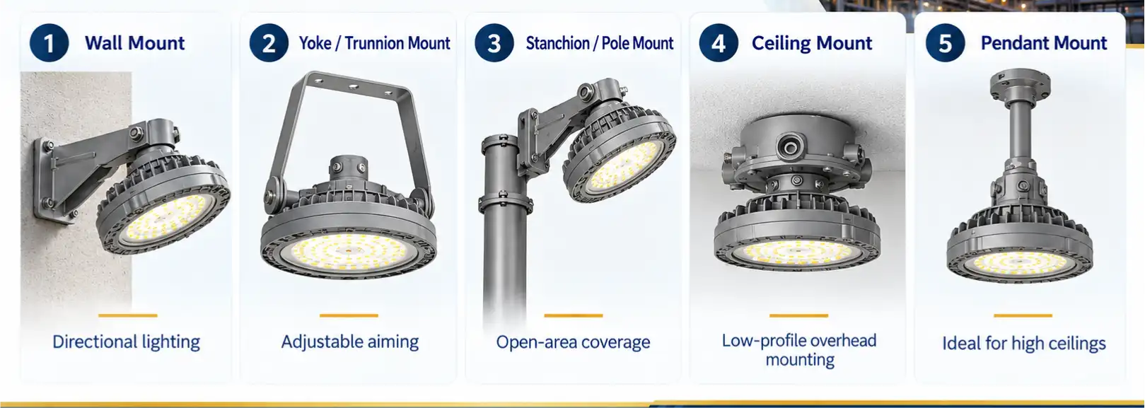
The most common mounting options for explosion-proof lights include wall mount, yoke or trunnion mount, stanchion or pole mount, ceiling mount, and pendant mount. Facility managers frequently ask whether the same explosion-proof light supports multiple mounting options, and the answer is yes. Most modern hazardous location fixtures feature modular housing designs that accommodate different installation methods simply by swapping the attached mechanical bracket. This comprehensive guide breaks down the engineering specifications, structural mechanics, and environmental variables required to help industrial facility managers select the safest and most compliant bracket configuration for their specific site conditions.
Five common ways to mount explosion-proof lights
Explosion-proof performance and safety certifications rely entirely on the complete assembled fixture system and its strictly compliant installation. The mounting hardware serves solely to position the light securely while maintaining the mechanical integrity of the heavy cast enclosure and the threaded conduit connections under physical stress. The following sections detail the mechanical characteristics and application logic for the five primary mounting configurations used in hazardous industrial environments.
Wall Mount
Wall mount brackets secure explosion-proof fixtures directly to vertical surfaces, structural steel columns, or reinforced concrete bulkheads using heavy-duty mechanical anchors or through-bolts. This configuration primarily provides directional illumination across perimeters, exterior walkways, or the outer faces of processing buildings. The lighting direction and adjustability depend heavily on the specific bracket geometry. While the industry frequently utilizes fixed 25 degree or 90 degree configurations, these specific angles are not universal standards; they depend entirely on the specific fixture model and the manufacturer's engineering design.
For example, a specialized explosion proof arm bracket measures exactly 5.6 x 5.6 x 4.2 inches and provides a fixed 25 degree mounting angle specifically engineered for compatible EXPLA, EXPLB, EXPLC, EXPLD, and EXPLG fixture series. This specific bracket features an IP67 rating and carries a 5 years warranty, ensuring long-term protection against dust and high-pressure water ingress in harsh exterior environments. Another common hardware configuration is the EXPHB3-MBWM bracket, which provides four threaded hubs for wiring and is compatible with 3/4" NPT, 1" NPT, M25*1.5 and M20*1.5 conduit sizes, allowing for versatile integration into international conduit systems.
Advantages: Wall mounting saves valuable horizontal floor space, keeps the fixture entirely clear of ground-level machinery or forklift traffic, and allows the electrical conduit to be routed directly along existing vertical structural supports.
Limitations: The illumination coverage remains strictly limited by the availability and location of vertical walls. Furthermore, mounting high-wattage fixtures too close to a wall can restrict convective airflow, potentially increasing the operating temperature of the LED driver.
Typical Applications: Exterior walls of oil and gas facilities, chemical plant perimeters, narrow industrial corridors, and above personnel doors in hazardous processing areas.
When to Choose: Select a wall mount explosion proof light when overhead ceiling structures are too high to provide effective ground-level foot-candles, or when the central floor space must remain entirely unobstructed for heavy operational logistics.
Yoke / Trunnion Mount
The yoke or trunnion mount utilizes a heavy-duty U-shaped metal bracket that attaches symmetrically to the sides of the light fixture housing. This mechanical design allows the entire fixture to pivot smoothly along a single horizontal axis. Installers can bolt the flat base of the U-bracket to horizontal ceilings, vertical walls, or solid ground surfaces, making it highly versatile. When facility managers ask when an adjustable yoke/trunnion bracket should be selected, the technical answer centers on dynamic lighting requirements. This bracket is absolutely required when the specific visual task demands high beam adjustability, or when the operational layout of the work zone changes frequently, requiring the light beam to be redirected without unbolting and reinstalling the entire fixture assembly.
To maintain the aiming angle, yoke mounts rely on heavy friction washers, toothed locking gears, or high-torque set screws located at the pivot points. The electrical connection for a yoke-mounted fixture typically requires a short length of explosion-proof flexible coupling to transition from the rigid facility conduit to the moving fixture housing, allowing the pivot action without breaking the flame path.
Advantages: Provides maximum mechanical flexibility for lighting direction control, allows precise targeting of the beam center, and supports installation on virtually any flat structural surface regardless of its orientation.
Limitations: The U-bracket assembly occupies more three-dimensional physical space than flush mounts. Additionally, the pivot points are highly susceptible to angle shifting if the locking mechanisms are exposed to continuous, high-amplitude mechanical vibration.
Typical Applications: Automotive or aerospace paint booths requiring targeted angled illumination, active loading areas, inspection bays, and temporary hazardous maintenance zones.
When to Choose: Deploy a yoke mount explosion proof light when the exact required beam angle cannot be determined precisely prior to installation, or when operational tasks require periodic, manual redirection of the light source by maintenance personnel.
Stanchion / Pole Mount
Stanchion or pole mounting involves securing the explosion-proof fixture to a tubular steel structure, such as an existing handrail stanchion, a catwalk guardrail, or a dedicated freestanding lighting pole. The mechanical connection is typically achieved via a slip fitter collar that slides over the pole and locks with heavy set screws, or through a direct threaded conduit connection. The resulting illumination direction is generally downward or set at a specific outward angle. Similar to wall mounts, configurations like a fixed 25 degree or 90 degree tilt depend entirely on the manufacturer's specific casting molds rather than an industry-wide structural mandate.
Hardware dimensions must match the facility infrastructure precisely to ensure a secure, vibration-resistant fit. For instance, a typical 90 degree wall mount bracket with tenon measures exactly 9.25" x 9.5" x 7" and provides slip fitter compatibility specifically for a tenon diameter of 2.38 inches. The wiring for stanchion mounts is usually routed internally up through the hollow pole, protecting the conductors from environmental degradation and mechanical impact before entering the fixture's explosion-proof junction chamber.
Advantages: Delivers high-elevation, broad-area lighting across wide, open platforms where no vertical walls or overhead ceilings exist to support other bracket types. It also utilizes existing structural guardrails, reducing the need for new steel fabrication.
Limitations: The maximum installation height is strictly limited by the structural bending moment and wind load capacity of the pole. Furthermore, maintenance access often requires specialized bucket trucks, temporary scaffolding, or hazardous climbing gear.
Typical Applications: Offshore drilling platforms, petroleum refineries, outdoor elevated walkways, and wastewater treatment catwalks.
When to Choose: Specify a stanchion mount when illuminating open-air industrial environments, multi-level processing platforms, or exterior storage tank farms that lack overhead structures but feature existing tubular steel guardrails.
Ceiling Mount
Ceiling mounting fastens the explosion-proof fixture directly and flush against the overhead structural deck, concrete ceiling, or horizontal steel support beams. This installation method requires specialized cast mounting hoods or integrated junction boxes that interface directly with the top of the fixture housing. For example, a standard V51 3/4 3-HUB CEILING MOUNT utilizes a 3/4 Inch interface size to secure the heavy fixture mechanically while providing feed-through threaded conduit access for the electrical conductors.
Because the fixture sits flush against the ceiling, the resulting illumination pattern projects strictly vertically downward, creating highly uniform, symmetrical light distribution across the floor plane. This mounting method requires careful consideration of thermal dynamics, as heat generated by the fixture naturally rises and can become trapped against the ceiling boundary layer, requiring fixtures with highly efficient external heat sinks.
Advantages: Maximizes the available vertical clearance in the facility for material handling equipment, and provides the most rigid, vibration-resistant structural connection among all available mounting types due to the lack of cantilevered moment arms.
Limitations: The beam direction is entirely fixed and non-adjustable. Maintenance access requires scissor lifts, boom lifts, or scaffolding, which can disrupt floor-level operations during servicing.
Typical Applications: Industrial chemical plants with standard ceiling heights, hazardous material storage warehouses, and enclosed pharmaceutical processing rooms.
When to Choose: Utilize ceiling mounts in enclosed facilities where overhead operating space is severely limited, the ceiling structure is robust enough to handle the concentrated point load, and uniform ambient floor lighting is the primary operational objective.
Pendant Mount
Pendant mounting suspends the explosion-proof light fixture below the ceiling structure using a vertical length of rigid metal conduit. In this configuration, the conduit serves dual critical purposes: housing the electrical wiring safely and acting as the sole mechanical support stem for the heavy fixture. Specialized cast fixture hangers facilitate this connection at the ceiling level, often incorporating ball joints to allow a small degree of plumb adjustment. A typical EFHC Fixture Hanger features a 3/4 Inch conduit size for the ceiling junction box connection and a 1/2 Inch fixture stem size for the vertical drop pipe.
To maintain explosion-proof integrity, every threaded connection in a pendant drop must be fully engaged, typically requiring a minimum of five full threads, and often secured with set screws to prevent rotational unthreading over time.
Advantages: Lowers the light source to the optimal working plane, effectively bypassing overhead HVAC ducts, chemical piping networks, and structural steel trusses that would otherwise block the light distribution and cast dangerous shadows.
Limitations: The suspended mass at the end of a rigid pipe creates a pendulum effect, making the entire fixture assembly highly susceptible to swaying, metal fatigue, and mechanical stress at the threads in areas with high wind loads or severe structural vibration.
Typical Applications: High-bay machining shops, tall aircraft hangars, and heavy manufacturing facilities with high roof decks.
When to Choose: Select a pendant mount when the facility ceiling is exceptionally high, and mounting the fixture flush against the deck would result in inadequate foot-candle illuminance levels at the ground working plane.
Mounting Type Comparison for Hazardous Locations
Understanding the distinct mechanical differences between wall, yoke/trunnion, stanchion/pole, ceiling, and pendant mounts is critical for specifying the correct hardware for a hazardous area project. The following matrix identifies which mounting type is suitable for different installation surfaces, their inherent adjustability, and their typical industrial applications.

| Mounting Type | Installation Surface | Adjustability | Best For | Typical Applications |
|---|---|---|---|---|
| Wall Mount | Vertical walls, structural columns | Fixed angle (varies by manufacturer model) | Perimeter illumination, saving central floor space | Chemical plant exteriors, narrow corridors |
| Yoke / Trunnion | Walls, ceilings, floors, steel beams | High (single-axis continuous pivot) | Precise beam targeting, variable work layouts | Paint booths, loading docks, inspection bays |
| Stanchion / Pole | Tubular steel poles, handrails | Fixed angle (varies by manufacturer model) | Open-air platforms lacking walls or ceilings | Refineries, offshore platforms, catwalks |
| Ceiling Mount | Overhead structural decks, concrete ceilings | None (strictly fixed downward projection) | Maximizing facility headroom, extreme stability | Warehouses, low-ceiling processing plants |
| Pendant Mount | High ceilings (suspended via rigid conduit) | None (strictly fixed downward projection) | Bypassing overhead structural piping obstacles | High-bay processing shops, tall hangars |
Factors to Consider When Choosing a Mounting Bracket
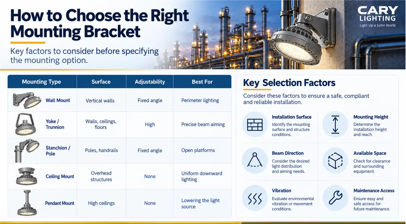
An explosion proof light mounting bracket demands careful evaluation of complex environmental, structural, and regulatory variables during selection. Failure to account for these specific engineering factors can compromise both the photometric lighting performance and the legal safety certification of the hazardous location installation.
Installation surface integrity dictates the baseline bracket selection. Solid concrete walls require heavy-duty expansion anchors and wall mounts, while open steel grating or tubular handrails necessitate stanchion mounts with slip fitters. The structural load-bearing capacity of the surface must exceed the weight of the heavy cast-aluminum fixture multiplied by the appropriate safety factor for dynamic loads.
Mounting height directly affects the photometric layout. The vertical distance from the active work plane determines whether a flush ceiling mount provides sufficient illuminance, or if a pendant mount is required to physically lower the light source to achieve the target foot-candles.
Beam direction requirements dictate the mechanical adjustability needed. Tasks requiring horizontal, lateral, or specifically angled illumination require wall or yoke mounts. Conversely, general ambient floor lighting relies on the symmetrical downward projection of ceiling or pendant mounts.
Available space and clearance limits often overrule other preferences. Low-clearance processing areas demand ultra-low-profile ceiling mounts to prevent catastrophic collisions with moving overhead cranes, automated guided vehicles, or forklift masts.
Maintenance accessibility must be engineered into the bracket selection. Brackets installed over active chemical vats, high-temperature furnaces, or moving machinery must allow for rapid, safe fixture replacement. Yoke mounts positioned on easily accessible catwalks often prove significantly safer and faster to maintain than pendant mounts suspended high over hazardous processing equipment.
Conduit and cable routing paths must align seamlessly with the bracket design. The mounting hardware must integrate with the facility's existing rigid conduit infrastructure. Brackets that feature integrated, threaded junction boxes simplify the wiring process and reduce the number of required explosion-proof seals, while bare brackets require the installation of separate external explosion-proof enclosures.
Fixture compatibility is non-negotiable. Brackets are engineered for specific fixture weights, center-of-gravity profiles, and thread pitches. A bracket designed for a lightweight linear strip light lacks the mechanical shear strength to support a heavy, high-wattage high-bay dome fixture.
Hazardous-location requirements dictate the fundamental design of the entire mounting system. The classification of the environment directly influences the permitted installation methods. A Class 1, Div. 1 location, defined as an area where flammable gases, vapors, or liquids are present continuously or frequently under normal operating conditions, requires the most stringent threaded conduit seals, explosion-proof flexible couplings, and heavily reinforced mounting interfaces to contain an internal blast. Conversely, a Class 1, Div. 2 location, where these flammable substances are present only under abnormal conditions such as an equipment failure, still requires certified brackets and secure mounting, but may allow for different, slightly less restrictive wiring methods depending on the local electrical code adoption.
NEC Code Requirements and Conduit Support for Mounting
A frequent and critical engineering challenge in hazardous locations involves the mechanical securing of the explosion-proof junction boxes that feed the lighting fixtures. Many heavy-duty explosion-proof boxes are intentionally cast without external mounting ears, flanges, or bolt holes to maintain the absolute integrity of their internal flame paths and prevent stress fractures in the casting. Instead of bolting the box directly to the building structure, the National Electrical Code (NEC) often dictates that the entire assembly must be supported entirely by the threaded Rigid Metal Conduit (RMC) entering the hubs.
This strict compliance logic means that the mechanical strength and safety of the installation rely entirely on how the conduit itself is strapped and anchored to the building structure. Proper, heavy-duty strapping prevents rotational forces, lateral sway, and sheer stress from compromising the precisely machined threaded explosion-proof joints. Many field installers report that rigid metal conduit strapping distance must be maintained strictly within 3 inches of the explosion-proof box to ensure adequate mechanical support and prevent joint deflection, though exact distance mandates always require verification against the local jurisdiction's active NEC cycle and the specific manufacturer's installation instructions.
| Component / Standard | Specification / Value | Functional Meaning for Installation |
|---|---|---|
| UL 844 | Certification standard | Mandates construction requirements for explosion-proof hazardous location luminaires. |
| Class I, Division 1 | Operating classification | Requires sealed containment where flammable gases exist during normal operations. |
| Class I, Division 2 | Operating classification | Governs locations where flammable gases are present only under abnormal failure conditions. |
| EFHC Fixture Hanger | 3/4-inch conduit, 1/2-inch rod | Adapts ceiling conduit drops to structural fixture support stems. |
| V51 Ceiling Mount | 3/4-inch hub size | Provides three threaded entries for rigid ceiling-supported hazardous lighting feeds. |
| EXPHB3-MBWM Bracket | 3/4" NPT, 1" NPT, M25*1.5, M20*1.5 | Connects fixtures using imperial NPT or metric threaded conduit entries. |
| Explosion Proof Arm Bracket | 5.6 x 5.6 x 4.2 inches | Sets structural footprint and standoff distance for hazardous arm-mounted luminaires. |
| Arm Bracket Angle | Fixed 25 degrees | Sets directional downward pitch for EXPLA, EXPLB, EXPLC, EXPLD, and EXPLG series. |
| Tenon Wall Bracket | 2.38-inch diameter, 9.25" x 9.5" x 7" | Mounts standard tenon-mount fixtures to vertical wall surfaces. |
| Enclosure Sealing | IP67 ingress rating | Prevents particle ingress and water immersion up to temporary submersion limits. |
If the rigid conduit is not properly secured close to the hub, the suspended weight of a pendant-mounted fixture or the extreme leverage exerted by a long wall-mounted arm bracket can cause the threaded connection to deform or fail entirely. A failed thread instantly voids the explosion-proof integrity of the system, allowing internal ignition flames to escape into the hazardous atmosphere, leading to catastrophic facility consequences.
Vibration Resistance in High-Impact and Offshore Applications
Industrial processing environments such as offshore drilling rigs, heavy metal stamping plants, and massive diesel generator rooms subject lighting fixtures to continuous, high-amplitude mechanical vibration. Selecting a mounting bracket in these high-impact zones requires analyzing the underlying physics of mechanical resonance and metal fatigue.
Every physical structure, including a cast aluminum mounting bracket, possesses a natural resonance frequency. When the external vibration frequency generated by heavy industrial machinery matches the natural resonance frequency of the mounting bracket, the mechanical displacement amplifies significantly. This phenomenon, known as harmonic resonance, leads to rapid microscopic metal fatigue in the bracket's stress points, the gradual loosening of explosion-proof threaded joints, and the premature failure of the internal LED drivers due to shattered solder joints.
To counteract this destructive force, heavy-duty explosion-proof mounting brackets utilize specific structural engineering modifications. Increasing the physical thickness of the cast aluminum walls or utilizing marine-grade 316 stainless steel alters the total mass of the bracket, thereby shifting its natural resonance frequency safely away from common industrial machinery operating frequencies. Furthermore, brackets designed specifically for high-vibration areas incorporate specific geometric casting shapes, such as triangular gussets and thick reinforcing ribs, to exponentially increase structural stiffness and provide mechanical damping effects.
In these severe high-vibration applications, long cantilevered structures must be strictly avoided. The longer the physical moment arm of the bracket, the greater the multiplied stress at the mounting base. Therefore, pendant mounts utilizing long rigid conduit drops are highly susceptible to catastrophic shear failure near heavy rock crushers or massive gas compressors. Instead, facility engineers should specify highly compact ceiling mounts that keep the fixture's center of gravity as close to the structural deck as possible, or utilize heavy yoke mounts equipped with specialized vibration-damping rubber isolators at the pivot points to absorb the kinetic energy before it reaches the fixture housing.
Frequently Asked Questions (FAQ)
Are mounting brackets universally compatible across different explosion-proof light brands?
Mounting compatibility is almost never universal. Thread pitches for conduit hubs, bolt hole patterns, weight load ratings, and center-of-gravity requirements vary drastically between different manufacturers. Always utilize the specific bracket engineered and listed for the exact fixture series being installed to maintain the safety certification.
Can the angle of an adjustable bracket be changed while the fixture is energized?
Adjustable brackets like yoke or trunnion mounts allow for precise angle changes, but physical repositioning should never occur while the fixture is energized in a hazardous location. Loosening the pivot bolts can temporarily compromise the grounding path or stress the explosion-proof flexible coupling. Always de-energize the circuit and verify the atmosphere before adjusting the beam direction.
How do facility managers choose between a wall mount and a stanchion mount for space utilization?
The choice between a wall versus stanchion mount depends strictly on the existing structural infrastructure. Wall mounts save central floor space but require flat, load-bearing vertical structures. Stanchion mounts consume a small footprint along walkways but are absolutely necessary when illuminating open steel grating platforms where vertical walls do not exist to support a bracket.
What specific measures prevent a pendant installation from swaying in high winds?
Pendant installations in outdoor or high-draft environments require engineered sway control. This is typically achieved by keeping the rigid conduit drop as short as physically possible, utilizing heavy-wall RMC instead of standard conduit, and installing a listed flexible explosion-proof coupling at the top ceiling connection to absorb lateral kinetic energy without fracturing the rigid threaded hub.
How does the hazardous location classification affect the choice of mounting bracket material?
Hazardous-location mounting selection must account for the ambient corrosives often present in these classified zones. While standard cast aluminum suffices for many dry indoor facilities, offshore platforms or chemical plants with high salinity and corrosive chemical vapors require brackets manufactured from copper-free aluminum with specialized baked epoxy powder coatings, or marine-grade 316 stainless steel, to prevent severe structural degradation and bracket failure.